About Electromagnetic Stirrer Inquiy
Electromagnetic stirrers are designed and manufactured to achieve optimum metallurgical quality improvements based on each customer’s specific plant and casting conditions. In order for KEMEIDA to submit a proposal for EMS that will best meet the requirements of a specific customer, it is important that the following questionnaire is filled out in as much detail as possible and returned to KEMEIDA together with the inquiry.
QUESTIONNAIRE FOR EMS (doc.) Download
About Lifting Electromagnet Inquiy
To help you get the suitable magnet for your application, you are reqested to give following information:
1. What shape of material are to be handled?
For example: steel scraps, bloom, plate or bar.
2. What are the dimensions & temperature of steel plate or bloom?
3. What’s the lifting capacity you expect?
4. What are the site conditions?
5. What is the lifting cacapcity of crane and hoist height?.
6. Do you need the control cubicle also?
About Separator Inquiy
To help you get the best magnet for your application, we should have the following information:
1. What are the materials you want to handle?
2. What kind of steel and iron do you want to remove?
3. What’s the handling capacity?
4. What kind of working site does the separator work?
5. What is width of the belt?
6. Do you want the electric controller?
About Electromagnetic Stirring
The use of electromagnetic stirring during metals solidification dates back to the 1930s,and a comprehensive review of the stirring activities up to the early 1980s was provided by Tzavaras and Brody. Like electromagnetic casting, electromagnetic stirring is produced by the Lorentz force generated by an a.c. inductor. Unlike electromagnetic casting where stirring occurs near the surface region, however, electromagnetic stirrers are designed to deliberately produce melt convection deep in the liquid pool near the solidification front. Thus, lower-frequency magnetic fields are used to allow the Lorentz force to penetrate deeply into the molten-metal pool.
Two types of electromagnetic stirrers are commonly used in practice: the linear stirrer and rotary stirrer. A linear stirrer operates basically the same way as an induction furnace. The design entails the placement of a stack of coils around the casting metal to generate a primary motion that recirculates along the casting direction. A rotary stirrer is basically an electric motor. It uses a rotating magnetic field to produce a swirling flow in the liquid pool. Figure 3 contrasts the linear and rotary stirring modes and the primary fluid motions in the liquids. The two modes may be applied either individually or in a combined fashion and stirring may be employed in various stages of solidification processes(i.e., in mold, below mold, and at the final stage of solidification).
Perhaps one of the major motivations for applying electromagnetic stirring during solidification processing comes from the understanding that a strong melt flow will generate strong shear stresses, and the shear stresses will shed away the newly formed dendrites near the solidification front.The newly formed dendrite debris is then transported into the bulk liquid pool of higher temperature by convection. Some of the dendrites are remelted and disappear while others survive and are transported back to the solidifying region. These surviving broken dendrites then form additional nucleation sites upon which further grain growth will occur, thereby resulting in grain refinement in the final casting products. This basic grain multiplication mechanism induced by strong electromagnetic stirring is depicted in Figure 4.
Aside from refining internal structures, electromagnetic stirring also has the advantages of homogenizing alloy elements, reducing porosity and segregation, and minimizing internal cracks. Table I summarizes the benefits of electromagnetic stirring when applied in the mold region (mold electromagnetic stirrer), below the mold or strand (strand electromagnetic stirrer), and in the final stage of solidification (final electromagnetic stirrer).
The Effects of Electromagnetic Stirring during the Continuous Casting of Metals
|
Mold Electromagnetic Stirrer |
Strand Electromagnetic Stirrer |
Final Electromagnetic Stirrer |
|
¡ª |
¡ª |
¡ª |
|
Surface Slags |
¡ª |
¡ª |
|
Break-Outs |
¡ª |
¡ª |
|
Subsurface Inclusions |
¡ª |
¡ª |
|
Pinholes |
¡ª |
¡ª |
|
Blowholes |
¡ª |
¡ª |
|
Columnar Structure |
Columnar Structure |
V-Segregation |
|
Internal Cracks |
Internal Cracks |
¡ª |
|
Center-Line Segregation |
Center-Line Segregation |
Center-Line Segregation |
Electromagnetic Lifting System Field Of The Invention
ELECTROMAGNETIC LIFTING SYSTEM FIELD OF THE INVENTION This invention is an electromagnet structure, particularly adapted to move ferrous metal workpieces onto and off of a supporting surface.
BACKGROUND OF THE INVENTION One method of manufacturing shaped ferrous metal workpieces from a large metal plate of ferrous metal utilizes a cutting table. A large ferrous metal plate is placed on a heat resistant cutting table and workpieces of various shapes are cut from the plate using laser beams, plasma beams, or flame cutting torches. The cutting process may be manual or automated. The result of the cutting operation is, typically, a large number of parts or workpieces of various sizes and shapes positioned within a skeleton like structure of the scrap remaining from the original plate. In order to make this cutting table process most efficient, it is desirable to provide a system for lifting the stock plate onto the table and positioning it, and then a system for very quickly picking up all of the workpieces, scrap, and the skeleton plate once the cutting is complete. It has been found to be very desirable to employ an electromagnetic system for not only initially positioning the stock plate on the cutting table, but also for picking up the workpieces which have been cut from the plate once the cutting has been completed. A number of problems, however, can result from the use of conventionally designed electromagnets for this cutting process. First of all, any electromagnetic system which is designed to cover a large surface area is typically formed of very thick core materials which are typically very heavy. In order to support the series of electromagnets typically required to cover large surface areas, and particularly when those electromagnets themselves are very heavy, often requires a very heavy structural framework for supporting the electromagnetics. Thus, the entire electromagnetic system and its supports are often very heavy and require a substantial amount of work to lift them, particularly if they are carrying the workpieces. This high weight for the electromagnetic system not only increases the energy requirements necessary to carry out the lifting function, but also increases the potential danger associated with heavy equipment suspended in the air.
Another problem with using conventional electromagnetic systems for the lifting system is that the conventional electromagnetics are typically constructed with circular coils which wrap around an oval track which is formed in the body of the core. In general, it is necessary to have numerous, closely-spaced coils, in order to assure that small workpieces will be effectively attracted to the magnet. At the ends of these tracks are inhomogeneous magnetic field structures which tend to form”weak spots”at each end of each series of electromagnetic coils. These”weak spots”are often ineffective at carrying out the lifting function, particularly for small pieces which are positioned at the outer edges of the cutting table. As a result, it is often necessary to build the magnet system far larger than what would otherwise be necessary and larger than the cutting table surface. The”weak spot”structure is shown in Figure 21 which is a bottom view of a conventional lifting system magnetic structure.
These and other difficulties experienced with the prior art devices have been obviated in a novel manner by the present invention.
It is, therefore, a principal object of the present invention to provide an electromagnet structure which is low in weight, and, more specifically, has a low weight-to-magnetic working area ratio, thereby producing a magnet which is efficient to use as a lifting magnet.
Another object of this invention is to provide an electromagnet structure that has a large magnetic working area which area has relatively uniform magnetic fields throughout and is free of magnetic”weak spots”, so that the magnet is capable of attaching small ferromagnetic objects at any point in its working area.
It is a further object of the invention to provide an electromagnet structure which is capable of being manufactured of high quality and at a low cost, and which is capable of providing a long and useful life with a minimum of maintenance.
With these and other objects in view, as will be apparent to those skilled in the art, the invention resides in the combination of parts set forth in the specification and covered by the claims appended hereto.
BRIEF SUMMARY OF THE INVENTION An electromagnet having a core with a plurality of elongated channels, a bottom opening to each channel, and a coil made up of a plurality of lengths of electrically conductive wire extending through each channel. The core has a top wall and a plurality of spaced parallel vertical walls which define the channels. The bottom end of each vertical side wall has horizontal flanges which form the poles of the magnet and also define the openings to the channels. Each pole has a different polarity from adjacent poles.
This invention may be viewed as electromagnet system, including an electromagnet structure which has a core and a coil, and a supply of electric current for energizing the coil and magnetically exciting the core.
This invention may also be viewed as electromagnetic lifting system including an electromagnet structure which has a core and a coil, a supply of electric current for energizing the coil and magnetically exciting the core, and a movement system adapted to provide controlled movement of the structure.
This invention can also be viewed as a cutting table lifting system, including a cutting table, a workpiece of ferrous material, an electromagnet structure which has a core and a coil, a supply of electric current for energizing the coil and magnetically exciting the core, said supply adapted to control the attraction of the structure to the workpiece, and a movement system adapted to provide controlled movement of the structure with respect to the table, said lifting system being adapted to place the workpiece on the table and to remove the workpiece from the table.
BRIEF DESCRIPTION OF THE DRAWINGS The character of the invention, however, may best be understood by reference to one of its structural forms, as illustrated by the accompanying drawings, in which: FIG. 1 is a front elevational view of an electromagnetic lifting system embodying the principles of the present invention; FIG. 2 is a fragmentary bottom plan view of the lifting system; FIG. 3 is a fragmentary top plan view of the lifting system; FIG. 4 is a fragmentary side elevational view of the lifting system; FIG. 5 is a front elevational view of a shield of non-magnetic material for application to the lifting system of the present invention; FIG. 6 is a front elevational view of the electromagnetic lifting system of the present invention which includes the shield of FIG. 5; FIG. 7 is a fragmentary side elevational view of the core portion of the lifting system; FIG. 8 is a fragmentary bottom plan view of the core; FIGS. 9-18 are operational views illustrating how the electromagnetic lifting system of the present invention is used for separating parts and scrap from a cutting table; FIG. 19 is a schematic end view of a prior art electromagnet; FIG. 20 is a schematic end view of the electromagnet of the present invention; FIG. 21 is a schematic bottom plan view of a prior art electromagnet; FIG. 22 is a schematic bottom plan view of the electromagnet of the present invention; and FIGS. 23 and 24 are schematic views of two possible winding strategies for the coil portion of the electromagnet of the present invention.
DETAILED DESCRIPTION OF THE INVENTION Referring to FIGS. 1-6, the electromagnetic lifting apparatus of the present invention is generally indicated by the reference numeral 10 and comprises a core, generally indicated by the reference numeral 12 and a coil, generally indicated by the reference numeral 14.
Referring also to FIGS. 7 and 8, the core 12 comprises a plurality of elongated channel beams, generally indicated by the reference numeral 16. Channel beams 16 are arranged side-by-side in a row and are fixed to a pair of structural beams 18 by nuts 17 and bolts 19. The structural beams 18 extend transversely of the channel beams 16 and are located at opposite ends of the channel beams. A pair of central structural beams 20 are located in the center of the channel beam 16 transversely of the channel beam. A cross beam 22 extends between the central structural beams 20 at a mid point of the structural beams 20.
The beams 20 are fixed to the channel beams 16 by nuts and bolts. A lifting ring 24 is fixed to the cross beam 22 for receiving a hoisting chain 26.
Referring again to FIGS. 7 and 8, each channel beam 16 has a top wall 24 and a pair of vertical side walls 26 and 28. The lower end of each side wall 26 and 28 has an inwardly extending horizontal flange 30. The top and side walls of each channel beam 16 defines a generally rectangular channel 32 and the inner ends of the flanges 30 define an opening 34 to the channel 32. Each pair of abutting oppositely extending flanges forms one of the poles of the core, generally indicated by the reference numeral 36. As shown in FIGS. 3 and 4, each coil 14 is made up of electrically conductive insulated wire located within the channels 32. Beginning with the first two channels 32, the electrically conductive wire is wound in several loops around the side wall pair 26 and 28 which separate the first two channels., Each side wall pair 26 and 28 function as a single side wall. The plurality of loops form a loop bundle 37. Each successive pair of channels 32 contain a loop bundle 37. All of the loop bundles 37 can be formed from a single continuous electrically conductive wire 39 as shown in FIG. 23 so that the loop bundles 37 are in series. Only one loop per loop bundle is illustrated in FIG. 23 for clarity. In the preferred embodiment, three successive loop bundles 37 are formed from a single wire. Additional groups of three loop bundles 37 are formed from additional wires. Current flow is indicated by the arrows. In another embodiment as illustrated in FIG. 24, each loop bundle, generally indicated by the reference numeral 37, is formed from a first wire 41 and a second wire 43. Current flow for each of the wires 41 and 43 indicated by the arrows. Current flow through wire 43 is counter to that of the current flow through wire 41. Each loop bundle in the embodiment of FIG. 24 comprises a plurality of loops from each of the wires 41 and 43. A partial loop for each loop bundle is shown in FIG. 24 for clarity of illustration. Loop bundles from wire 41 alternate with loop bundles from wire 43. This provides an option of reducing the magnetic force of the magnet by 50% by deenergizing one of the wires 41 and 43. A plurality of vertical stops 38 of non magnetic material are fixed to the flanges 30 for propping the outer ends of each loop bundle 37 at an upward angle at the end of each channel beam. Each end of each channel beam 16 tapers downwardly and outwardly from the top wall 24, as shown in FIG.
1, so that the end of each loop bundle 37 is located above the tapered portion of the channel beam.
Referring to FIGS. 5 and 6, the electromagnet 10 is covered with a shield, generally indicated by the reference numeral 40. The shield 40 is made of a non-magnetic material, i. e. stainless steel and comprises a bottom wall 42, a pair of vertical side walls 44 located at opposite ends of the shield, and a pair of supporting walls 46 fixed to the upper ends of the vertical walls 44. Each supporting wall 46 has a horizontal inwardly extending component 48 and a vertical downwardly extending component 50. The lower end of each vertical component 50 is spaced from the bottom wall 42 and has a horizontal flange or foot 52. The shield 40 is applied to the electromagnet 10 so that the bottom wall 42 is located below the poles 36 and the openings 34. The vertical end walls 44 are located outside of the stops 38 and the supporting wall 46 extends above the structural beams 18 so that the feet 52 rest on the top walls 24 of the channel beams 16. Although the shield 40 is shown as a single integral piece, it can be fabricated from a plurality of pieces.
In addition to the overall effectiveness of the magnet system in lifting both the frame and workpieces from a cutting table on which the workpieces had been laser cut from a starting material plate, there is a separation aspect of the present invention. The”frame- workpiece separation feature”aspect of the present invention is shown in FIGS. 9-18 and essentially functions as follows. After a metal plate has been laser cut into a frame and a large number of workpieces, the entire resulting structure (both frame and workpieces) are engaged by the electromagnet and lifted off of the cutting table. The electromagnet is then positioned over a scrap table. The voltage to the magnet is then reduced to zero and the electromagnet slowly begins to lose its magnetism. After a period of time, but generally before the magnetism reaches zero, the frame or scrap falls from the magnet, leaving only the workpieces magnetically connected to the magnet. At this point, the voltage is immediately reapplied to the magnet and the workpieces remain attache to the magnet. The magnet is then positioned over a workpiece collection area. The voltage is again reduced to zero and, eventually, the magnetism reaches zero and the workpieces fall from the electromagnet into a workpiece collection area. In this way, the workpieces are easily separated from the frame or scrap. The theoretical reason for the scrap falling off of the magnet first is not entirely understood.
Considering the”frame-workpiece separation process”more specifically, as shown in FIG. 9, the process begins with the electromagnet 10 suspended over a work table 45. A workpiece plate, generally indicated by the reference numeral 56, is shown cut into individual workpieces 58 and 60 surrounded by a frame 62. FIG. 9 shows the workpiece as it has just been cut into the frame 62 and the individual workpieces 58 and 60. As shown in FIG. 10, the voltage is at zero and the magnetic force is at zero.
In FIG. 11, the electromagnet 10 has been lowered to contact the workpiece plate 56.
As shown in FIG. 12, the voltage has been raised to voltage V I and the magnetism increases to magnetic force MI.
As shown in FIG. 13 and 14, the electromagnet 10 is lifted and, because the workpiece plate 56 is attracted to it, the workpiece plate 56 is lifted along with the electromagnet 10. The voltage remains at voltage V and the magnetism remains at magnetic force M1.
In FIG. 15 and 16, the electromagnet 10 is moved over to a scrap table, and the voltage is dropped to zero. Slowly, the magnetic force drops from magnetic force MI to lower values. Because it has been found that a greater magnetic force is required to hold the frame against the magnet than is required to hold the workpieces against the magnet, as the magnetic force lessens, the frame 62 drops off first. Once that happens, the voltage is returned to voltage VI and the magnetic force returns to magnetic force M1.
As shown in FIG. 17 and 18, the electromagnet 10, carrying the workpieces 58 and 60, is then moved to a workpiece collection table 64. At that point, the voltage is dropped again to zero. The magnetic force decays to zero and the workpieces fall off onto the workpiece collection table 64. The electromagnetic 10 can thereafter be returned to the cutting table 45 to pick up another cut up workpiece plate.
The voltage to the electromagnet 10 can be controlled by the operator through a manually actuated voltage regulator., The voltage to the electromagnet 10 can also be controlled automatically by a voltage regulator operatively connected to control switches at the scrap table and the workpiece collection table. The control switches can be of a type which are mechanically actuated or electronic proximity switches which are actuated in the presence of metal such as that of the electromagnet.
A less sophisticated and simpler method of separating the workpieces from the frame makes use of flat permanent bar magnets. Prior to the deployment of the electromagnet, several spacer bars are placed on the frame at spaced locations. The spacer bars are of a non- ferrous material such as aluminum. However, bars of a ferrous material can be used as well as permanent bar magnets which will stay in place on the frame. The electromagnet is lowered toward the frame until it rests on the spacer bars which create spaces between the frame and the electromagnet. The frame and workpieces are lifted by the electromagnet and positioned over the scrap table. A pry bar is inserted in one of the spaces between the frame and electromagnet. The frame is forced away from the electromagnet by the pry bar so that the frame drops to the scrap table. The workpieces continue to be held by the electromagnet.
The workpieces are then carried to the workpiece collection table. The electromagnet is then deenergized which allows the workpieces to fall to the workpiece collection table.
The electromagnet 10 of the present invention is capable of loading and unloading a laser-, plasma-, or flame cutting table fully loaded with cut products in one cycle, without microjoints being necessary. In comparison to electromagnets currently in use such as multiple by-polar or three pole magnets and permanent pelletizing magnets, the weight of the electromagnet 10 of the present invention is very low, preferably below the product’s weight.
As a result, the initial cost of the magnet 10 is lower than existing magnets and the operating cost is also lower since less energy is needed to operate the magnet. There is a full magnetic area capable of picking up small cut products of typically 50 mm, or less in diameter.
Traditional magnet construction for cutting table lifting systems normally yields high weights. This is because, as shown in FIGS. 19 and 21, traditionally, electromagnet construction for lifting systems employ thick and heavy soft iron or steel cores 66. The core 66 has channels 67 which contain coils 65. The north and south poles are indicated by the reference numerals 71 and 70, respectively. Since the cutting table lifting system application typically does not require high flux densities, core cross sections can be reduced drastically, resulting in extreme low weights. Secondly, the need of magnetically”weak”zones at both outer edges of the magnetic area is eliminated. The weak zones of the prior art electromagnets are indicated by the reference numeral 68 in FIG. 22. This loss of magnetic area is the result of the space required for the”coil turn”or bend. In the present invention, the coil turns or ends of the loop bundles 37 are positioned on top of the tapered end of the core allowing the poles 36 to run all the way to the edge of the magnet.
With five U-channels of 50 mm x 25 mm x 8 mm x 2 mm cross-section (width x height x edge x thickness) and length 250 mm, giving a total area of 250 mm x 250 mm, the following results were measured: Plate size: 150 mm wide, covering three channels (outer channels covered by extra plate), 250 long and 15 mm thick Air gaps: 0.8,2,4 mm (stainless plate in between channel and plate).
Actual air-gaps are bigger because of channel unflatness, edges not perpendicular and edge radius (3 mm). The total effect is estimated between 0.5 and 1 mm.
All forces mentioned for these examples are for a plate under test of 250 mm 150 mm x 5 mm unless stated otherwise.
Forces in kgf (kilogram (force)) (gm-gf-cm-sec system) Amp turns Air Gap=0.8 mm 2 mm 4 mm 131 1.2 0.2 0 264 5.2 1.2 0.6 399 10.2 3.2 1.2 536 14.8 5.7 2.2 675 21.2 8.2 3.7 A plate of 250 mm x 150 mm x 15 mm weighs 4.4 kgf.
In order to hold a plate of 15 mm thickness with a safety factor of two at 0.8 mm gap, approximately 365 ampere turns are needed based on above measurement results.
Both finite elements and a simple circuit analysis give about the same values (with +/- 10%). These values are much higher than measured. The difference can be explained by the fact that actual air-gaps are bigger than just the thickness of the inserted stainless plate as used in the calculations.
For example, for a channel as described above.
Ampere turns: 399 Air-gap Measured forces Calculated at air gap as Calculated with an used in measurements. additional air-gap of (circuit analysis) 0.5 mm 0.8 10.2 15.8 9.4 2 3.2 5 3.5 4 1.2 1.55 1.3 The extra internal gap needed to make the calculations fit is well within the range estimated from the observed unflatness of the test piece.
The conclusion is that the circuit approach can be used to estimate the performance of other cross-sections. In evaluation of designs, we need to use at least 0.5 mm extra internal gap is required. An extra internal gap of 1 mm is best.
Channel thickness Reducing channel thickness to 1 mm results in some 45% force loss.
Reducing to 1.5 mm results in 15% force loss.
A choice of 2 mm is appropriate.
Edge size There is an optimum choice for edge size. In general, the bigger the edge size, the less ampere turns are needed to drive sufficient magnetic flux over the gap into the target plate. On the other hand, the leakages will increase with larger edges, resulting in more flux through the steel top of the channel and consequently, also more saturation on that spot. An extreme case of no force at all is found if the edge is so big that the channel is closed. The optimum depends on ampere turns available (399), total air-gap (say 1.5 mm), channel thickness (say 2 mm) and channel width (50 mm assumed).
Edge (mm) Force (kgf) 8 6 12 7.4 16 8.1 20 8.1 22.5 7.8 Choice of channel sizes.
A standard U-channel beam can be employed.
Some standard channels are: A 40mm x 20mm x 10mm x 2mm, a bit small B 80mm x 40mm x 16mm x 2mm, too big for small pieces.
Channel size A could be to small for many applications and channel size B could be to big for applications having small pieces.
Manufactured channel.
Manufacturing by bending is not very practical because of the large edge required.
An alternative is to use standard rectangular thin walled tubing and to mill an opening or slot lengthwise. With this method, cores can be made having any desired channel size.
A testing was made beginning with small standard channel irons or beams. The reason for this, besides it being readily available, is that the performance on small work pieces is expected to be better than with the use of larger channel irons or beams.
If the edges are big, then the flux does not need the surface of a small piece as a conductor: all flux can pass through the rest of the steel edge alongside the piece. There may be a limit to the edge size is half of the smallest piece (say 12 mm). This, however, could not be verified. For a proper best laser cut, parts are needed since the air gaps between the cut parts play an important part in holding performance.
Expected performance.
Given a coil with 450 Amp. turn and a channel of 40 mm x 20 mm x 10 mm x 2 mm, holding forces are calculated at: Air gaps Forces at 250 x 150 x 15 (mm) plate Maximum plate thickness mm kgf mm 1.5 13.6 46 3 4.4 15 Expected peak performance at 1000 Ampturns: The magnet is expected to pick up 15 mm material at a distance of: 7 mm.
This is acceptable Coil design.
The experimental channels were observed to run hot (not touchable) at 117 Watt heat input over a total channel length of 1.25 meters. With half the best input (45 Watt/meter channel) temperatures were acceptable. Based on this, a coil was designed for a 2.5 x 1.25 meter magnet with the following parameters: Voltage: 246 VDC Wire: 40 turns of 2.5 mm squared cross-section (litze wire) Ampere-turns (continuously): 450 Power”continuous””: 2750 Watt or 35 Watt per meter channel.
Peak Values: 1000 Amp turns (4 x bigger forces) 550 Volts peak, 13.75 kW Conclusion with respect to target weight.
In the above description, the general design of a cutting table lifting magnet is described So far this approach gives a magnet with a weight of: Steel channels + 0.8 wear plate: 145 kgf Coil copper wire: 65 kgf Structural parts: variable The target (equal to plate weight) seems feasible.
The preferred cross-section of the channels, disregarding the air gap, is square.
However, the channel cross-section could be rectangular, with the air gap on a long or a short side. Also, but substantially less desirable, the cross-section could be triangular or round. In fact, the cross-section can be any shape, but a shape that allows the air gap side to be flat and of maximum width, for example, a semi-circle with the air gap on the diameter side, is much preferred.
It is obvious that minor changes may be made in the form and construction of the invention without departing from the material spirit thereof. It is not, however, desired to confine the invention to the exact form herein shown and described, but it is desired to include all such as properly come within the scope claimed.
Lifting and dropping objects
The magnetic strength of an electromagnet depends on the number of turns or wire and the current through the wire, and the size of the iron core. This allows electromagnets to be made much larger and stronger than a natural magnet, such that they can pick up very large objects.
Also, when you turn off the electricity to an electromagnet, the magnetism is also turned off. Thus, an electromagnet can be used to pick up a piece of iron and then drop it someplace else.
Crane uses electromagnet to pick up junked car
Strong electromagnets are often used in areas of heavy industry to move large pieces of iron or steel. They are commonly employed in junkyards, where a crane with a huge electromagnet is used to pick up, move and drop old, junked cars.
What is an electromagnet?
An electromagnet is simply a coil of wire. It is usually wound around an iron core. However, it could be wound around an air core, in which case it is called a solenoid. When connected to a DC voltage or current source, the electromagnet becomes energized, creating a magnetic field just like a permanent magnet. The magnetic flux density is proportional to the magnitude of the current flowing in the wire of the electromagnet. The polarity of the electromagnet is determined by the direction the current. The north pole of the electromagnet is determined by using your right hand. Wrap your fingers around the coil in the same direction as the current is flowing (conventional current flows from + to -). The direction your thumb is pointing is the direction of the magnetic field, so north would come out of the electromagnet in the direction of your thumb. DC electromagnets are principally used to pick up or hold objects.
When connected to an AC voltage or current source, the electromagnet will be changing its flux density as the current fluctuates. The polarity of the magnet will also change as the current reverses direction every half cycle. AC electromagnets can be used to demagnetize objects (like TV screens, audio tapes, vcr tapes) or to hold objects. However, due to the inductance of the electromagnet, the AC current that will actually flow will be reduced when compared to a DC voltage equal to the RMS value of the AC voltage feeding the electromagnet.
The key importance of an electromagnet is the ability to control the strength of the magnetic flux density, the polarity of the field, and the shape of the field. The strength of the magnetic flux density is controlled by the magnitude of the current flowing in the coil, the polarity of the field is determined by the direction of the current flow, and the shape of the field is determined by the shape of the iron core around which the coil is wound.
Here is an example of the yoke of a TV. It is made of two sets of electromagnets, perpendicular to each other, and mounts onto the neck of the TV tube. The current flowing through these wires controls the electron beam going to the screen of the TV, causing the beam to trace out a raster or series of horizontal lines, one after the other, from the top of the screen to the bottom, and then back to the top again for the next frame. This creates the picture we see on the TV screen. One set of windings moves the electron beam from left to right, the other set moves the electron beam from top to bottom.
Winding a coil
Before you can start with the construction of an electromagnet, you first need to figure out the following:
1. What will the core be made of
2. What magnetic flux density are you trying to achieve
3. How many turns will be required for this along with
4. How many amps will be flowing through the wire
5. How big will the wire have to be to handle the current
6. How much surface area will you have for cooling the coil
7. How big will the electromagnet be due to the above
8. What voltage rating will the insulation of the wire have to withstand
9. What will be the inductance of the electromagnet
10. Obtain the core, wire, bobbin (form for the winding)
11. Wind the coil
12. Test the electromagnet
As you can see, there may be some times as you go through these steps that once you get an answer, you may have to go back a step or two and make some modifications, and recalculate. This is an iterative process.
To help, I use the following excel spreadsheet. Please feel free to use it. No warranties are implied. There may be errors, but I don’t think so. There is definitely room for improvement. Coildata excel file. Simply save it to disk, and then open it. Fill in the data needed in the green boxes. It will calculate the length of wire in a coil, the resistance, and get an approximate inductance for an air core if you want to play with some numbers.
Here are some excellent sources for help in building an electromagnet or coil.
A couple of things to keep in mind:
1. Use magnet wire with an enamel coating
2. If winding it onto a metal bar or bolt, first wrap the metal with one or two layers of electrical tape so the winding does not short out to the metal.
3. It takes time and care to do a clean, even winding.
4. After the first layer, wrap the layer with a thin piece of paper, or another layer of electrical tape, to provide a smooth surface for the second layer to lay on. Repeat this for each layer, or at least for every three layers.
When working with electromagnets, I have found that having a variac (a variac is a variable autotransformer) has been a great help. This provides a variable AC voltage source. When you plug something into it, you can adjust the output voltage anywhere from 0 to 140Vac. I start with it at zero, then slowly bring it up, watching the current and voltage. This way, I have control over what happens if there is a problem or a limitation. By connecting a diode bridge to the output of the variac, you also get a variable DC voltage source. They are rated by how much current they can handle. Choose one that can handle 2 or 3 amps minimum. As the amp rating goes up, so does the price. The cost of $100 is not bad for a 10 amp unit with a built in ammeter (a meter that measures amps)
Transformers
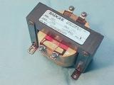
A transformer is simply two electromagnets which are magnetically coupled together. There is electrical isolation between the two windings, but power can be transferred from one winding (the primary) to the other winding (the secondary) via the alternating magnetic field. They work on AC voltages. The ratio of the secondary output voltage to the primary input voltage is equal to the ratio of the number of turns in the secondary winding to the number of turns in the primary winding. (i.e., Vout/Vin = Nsecondary/Nprimary)
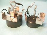
The photo on the left is a control transformer, and takes 230Vac in and drops it to 115Vac out for control circuits in industry. You can also turn it around and put 115Vac in and get 230Vac out. Transformers have a kVA rating which is the rated output Voltage times the rated output Amps divided by 1000. The one above is rated at 0.200kVA or 200VA. The two photos on the right show how to demonstrate the transformer action using two coils and the AC electromagnet from our electromagnet experiments.
Here is a source for what is needed to design and build autotransformers and electromagnets:
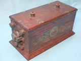

This transformer was called a Sparker or Ignition coil, used to create the spark needed for the spark-plugs in cars from the ’30s. It has a few turns for a primary winding, and lots of turns for a secondary winding. The mechanism at the end would open and close the circuit several times a second creating an AC like voltage on the primary (Since it was operated from a 12V battery, and transformers don’t work on DC, a method was needed to create an AC type of voltage on the primary coil). The secondary has thousands of turns on it, creating a high voltage of around 30,000V which will arc about 10mm through the air.
Jacob’s Ladder using a neon sign transformer
This Jacob’s Ladder uses a transformer which creates 15,000Vac on the secondary coil when 120Vac is applied to the primary coil. I built a box around the unit I show here. It has a Plexiglas front to keep curious fingers away from the wires. Be very careful with this!
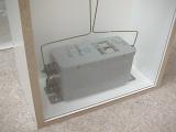
Battery Powered Electromagnet capable of holding 500 lbs!
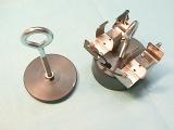

This is a lifting electromagnet from www.sciencefirst.com which is capable of holding 500lbs with just 2 D cell batteries! It costs about $55, but is quite a nice unit! It is their model number 20-035. They also have a slightly smaller electromagnet, model number 20-030, for about $47, which will hold 200lbs with just 1 D cell battery! The smaller unit is also available from ScientificsOnline (Edmund) as P/N 60-435.
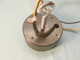
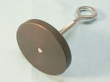
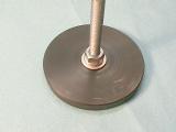
It is made of two parts – the yoke which also contains the coil, and the plate. The secret to the large holding force is that the plate and yoke are carefully machined so that there is no gap between them when they are placed together. It came with some excellent instructions on experiments you can do with it. However, I modified the larger unit a bit in order to make it easy to use on my wooden stand. Here’s what I did.
First, I removed the battery holders that came with it. Then I soldered longer wires to it, along with two banana plugs and a 9v battery clip in order to connect an ammeter in series with either a 2 cell AA battery holder or a 4 cell AA battery holder from Radio Shack. I also put a cable clamp on it so there wouldn’t be any strain on the wires from the coil assembly. Then I put a longer eye bolt into the plate, and secured it with a flat and lock washer.
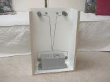
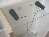
The Plank
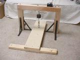
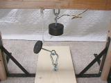
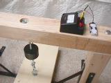

The wooden stand is made from a 4×4, 30″ wide, and the two vertical supports are 18″ tall each. The flat board or plank on the floor is a 2×10, and is 36″ long. The cross piece at the end of the 2×10 is a 2×4, 30″ long, to help stabilize the 2×10 when someone is on it. The photos show the construction details. The bolts on the horizontal 4×4 piece are 1/2″ x 8″ carriage bolts. I also have a string on the plate so that it won’t crash to the floor or to the plank.
The demonstration calls for a volunteer who will walk the plank toward the electromagnet. When he is standing at the electromagnet, it is then holding his full weight. If someone (an anchor person) were to stand on the end of the 2×10 where it is attached to the 2×4 cross piece, and the volunteer were to stand on the 2×10 at the far end, then the electromagnet would be holding 1.5 times the volunteer’s weight. (The anchor person will need to weigh at least half of the volunteer’s weight, otherwise the anchor person will be lifted up, like a see-saw!) When the volunteer is on the plank near the electromagnet, then disconnect the battery and watch the plate of the electromagnet pull away from the yolk of the electromagnet, causing the volunteer to drop about 1.5″ to the floor – proving that the batteries were able to convert enough chemical energy into electrical energy, the electromagnet’s coil was able to convert the electrical energy into magnetic energy, and the electromagnet’s yoke and plate were able to convert the magnetic energy into mechanical energy, in order to hold the volunteer’s weight! Pretty amazing!
With four AA batteries, I know it can actually hold at least 300lbs. With two AA batteries, I know it can hold at least 225lbs, but less than 300lbs. I wanted to use AA batteries instead of D batteries since they were smaller and the effect is more dramatic! I call this demo “The Plank”!
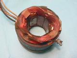
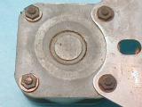
Audio Speakers
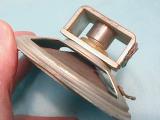

Speakers are made by placing a one layer coil of wire, wound onto a tube, into a magnetic field. The end of the tube is attached to the center of the paper cone of the speaker. When current is passed through the coil, a force is created on the coil, causing it and the tube to move within the magnetic field. When the current reverses direction, the coil and tube move in the opposite direction. This uses the Left Hand Rule.
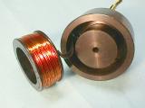
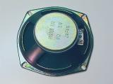
The photos above show a speaker and a magnet used for a speaker coil and its tube. The field is between the center post and the outer portion of the circular slit.
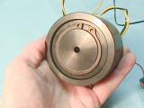
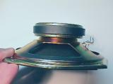
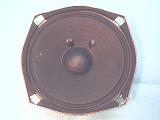
The speaker shown in the lower three photos will be dissected so you can see what the insides are like.

First, cut the wires going to the terminal strip. Then take a mat knife and carefully cut the cone around the edge. Let the knife follow the metal frame.
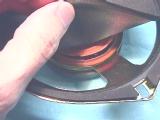


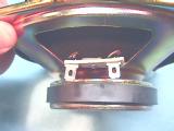
Next, you will need to hold the cone away as you carefully cut the inner paper disk, usually brown colored. You can then lift the cone and voice-coil assembly out of the magnet and frame. You can see how the magnet is made with a circular slit in it, where the center is a South pole, and the outside ring is a North pole (at least in this speaker). As current flows through the coil, it interacts with the magnet. The faster the current changes direction (the higher the frequency of the signal), the faster the cone moves in and out creating a higher frequency sound. The larger the magnitude of current, the farther the cone travels in and out of the magnet, the louder the sound. Connecting a battery to the speaker will cause the cone to pull in or push out a bit and stay there as long as the battery is kept connected. Reversing the battery connection will change the direction the cone moves (if it went out first, changing the battery around makes it go in the second time). Use a 1.5V battery for this test. This same effect is also demonstrated with the Fleming Left Hand Rule demo.

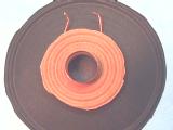
These are close-ups of the magnet, and the cone and voice-coil assembly. The voice-coil is the electromagnet, or solenoid. It is made with a very fine (small diameter) wire, with only two layers. It is then soldered to the flexible wires which you see on the left which attach to the terminal block. These wires are very flexible since the whole speaker cone goes in and out of the magnet in order to create the sounds.

The speaker in the upper left is one like the 5″ speaker cut open above. The larger speaker is a 15″ woofer from Radio Shack. Place some small wooden or glass beads into the middle of the speaker cone, and attach a signal generator to the speaker terminals. As you vary the frequency and volume, the beads start to dance on the cone. Fun to watch!
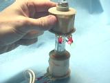
Make A Speaker!
Have you ever wanted to make your very own, working speaker? Here’s a great way to make one, and it’s simple, too! I am grateful to Michael Gasperi for his suggestion and for this kit that he created.
The materials you will need are:
24″ of 30AWG enamel magnet wire (from Radio Shack, p/n 278-1345B)
1.5″ brass-coated steel brad
ceramic magnet, 0.5″ diameter, 3/16″ thick (from Radio Shack, p/n 64-1883)
a 1.5″ square piece of 100 grit sandpaper
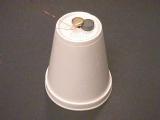
a styrofoam cup

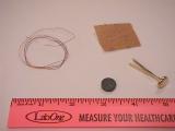
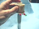
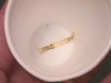
Take the wire, leave about 4″ for a connection lead, and wrap the rest of it around the brad near its head. Keep the coil on the brad within 3/16″ of the head as shown below. Again, leave about 4″ at the end of the winding in order to make a connection to the coil.
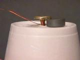
Now, place the magnet under the head (it will stick to the head of the brad) and press the brad into the bottom of the styrofoam cup. Separate the two tines of the brad and press them against the inside bottom of the cup as shown here.
Finally, take the sandpaper and clean about 3/4″ of each end of the wires from the coil in order to remove the enamel insulation so you can make an electrical connection to the coil. That’s it! Just connect the two ends of the coil to a radio jack and you’ll be able to hear the music.
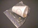
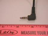
If you want, find an old, unused set of headphones and cut off the plug with some of the wire attached to it. Solder the pair of wire ends to the ends of the coil (one insulated wire to one end of the coil, the other wire of the pair to the other end of the coil). Then you can plug it in directly. (You could also buy a 1/8″ mini plug with alligator clips from Radio Shack, p/n 42-2421, and clip that onto the ends of the coil.)
Electric and Magnetic Sources
Electric sources are inherently “monopole” or point charge sources. Magnetic sources are inherently dipole sources – you can’t isolate North or South “monopoles”.
The electric field of a point charge is radially outward from a positive charge. The magnetic field of a bar magnet.
How Electromagnets Work-The Coil
The Coil
The figure below shows the shape of the magnetic field around the wire. In this figure, imagine that you have cut the wire and are looking at it end-on. The green circle in the figure is the cross-section of the wire itself. A circular magnetic fielddevelops around the wire, as shown by the circular lines in the illustration below. The field weakens as you move away from the wire (so the lines are farther apart as they get farther from the wire). You can see that the field is perpendicular to the wire and that the field’s direction depends on which direction the current is flowing in the wire. The compass needle aligns itself with this field (perpendicular to the wire). Using the contraption you created in the previous section, if you flip the battery around and repeat the experiment, you will see that the compass needle aligns itself in the opposite direction.
 Magnetic field of a wire |
Because the magnetic field around a wire is circular and perpendicular to the wire, an easy way to amplify the wire’s magnetic field is to coil the wire, as shown below:
 One loop’s magnetic field |
For example, if you wrap your wire around a nail 10 times, connect the wire to the battery and bring one end of the nail near the compass, you will find that it has a much larger effect on the compass. In fact, the nail behaves just like a bar magnet.
 A simple electromagnet |
However, the magnet exists only when the current is flowing from the battery. What you have created is an electromagnet! You will find that this magnet is able to pick up small steel things like paper clips, staples and thumb tacks.